In this guide

  1. Safety before touching wiring
  2. How thermostat control circuits work
  3. Thermostat terminal chart
  4. Why wire colors cannot be trusted
  5. Common system wiring patterns
  6. R, Rc, Rh, and jumpers
  7. C-wire power and adapters
  8. Heat-pump O/B wiring
  9. W2, AUX, E, and staging
  10. Safe replacement sequence
  11. Common mistakes and symptoms
  12. Professional diagnostic sequence
  13. Repair vs. thermostat replacement
  14. Official wiring sources
  15. Related diagnostic guides
  16. 12 FAQs

Start safely

Before touching thermostat wiring: identify the voltage and the system

Most central HVAC thermostats in Texas use a nominal 24-volt alternating-current control circuit. That does not make every thermostat installation a safe or universal do-it-yourself project. Line voltage is present inside furnaces, air handlers, condensers, heat kits, disconnects, and many zone-control cabinets. A low-voltage short can also blow a fuse, damage a transformer or circuit board, chatter a contactor, or command equipment in the wrong mode.

First determine whether the wall control is a standard low-voltage thermostat. Standard systems often have small 18- to 22-gauge conductors connected to lettered terminals such as R, C, Y, G, W, and O/B. Electric baseboard and some wall-heater controls may switch 120 or 240 volts and use thicker conductors, wire nuts, or line/load markings. Millivolt fireplace and gravity-heater controls are another category. A common smart thermostat is not automatically compatible with line-voltage or millivolt equipment.

  1. Find the exact thermostat model. Use the label behind the faceplate, the device menu, or the original manual. Terminal behavior and internal jumpers vary by model.
  2. Identify the HVAC equipment. Determine whether the home has a gas furnace with AC, electric air handler with AC, heat pump, dual-fuel system, boiler, zone panel, package unit, or communicating equipment.
  3. Take clear photos before disconnecting anything. Capture the terminal letters, wire positions, jumpers, and enough wall area to keep each conductor visually distinct.
  4. Label conductors by terminal. Mark the wire that was on Y as Y, the wire on G as G, and so on. Do not label by color alone.
  5. Turn off power to the indoor and outdoor equipment. The thermostat is usually powered by the indoor unit, but a complete service-safe shutdown may require more than one breaker or disconnect.
  6. Do not bypass safeties. A blower-door switch, condensate float, fuse, pressure control, or equipment lockout is part of the diagnostic information.

Stop immediately in these wiring situations

Do not proceed as a basic thermostat swap if you see thick line-voltage conductors; wire nuts in the thermostat box; terminals labeled 1, 2, 3, 4 or A, B, C, D; separate Rc and Rh conductors; a zone panel; a proprietary equipment interface module; more stages than the new thermostat supports; burned wiring; water at the equipment; or a low-voltage fuse that opens again. Those conditions require system-specific diagnosis.

Control theory made practical

What a thermostat actually does

A conventional thermostat is primarily a control switch. The HVAC transformer supplies control power to R. When cooling is needed, the thermostat typically connects R to Y. When the indoor fan is requested, it connects R to G. Conventional heating usually connects R to W. A heat-pump thermostat may also energize O/B to position the reversing valve. A powered smart thermostat uses R and C to run its display, processor, sensors, radio, and internal relays.

The thermostat does not necessarily power the compressor, blower motor, or heat strips directly. Its low-voltage outputs are interpreted by the furnace board, air-handler board, zone panel, equipment interface module, contactor coil, sequencer, or communicating controller. That is why a thermostat can show Cool On while the outdoor unit remains silent: the call may be leaving the thermostat but getting interrupted by a safety, broken conductor, control board, contactor, breaker, capacitor, motor, or compressor fault.

Power path

R → thermostat electronics or relay → C powers many modern thermostats. A missing common, loose terminal, open door switch, raised float, blown fuse, or weak transformer can make a thermostat blank or unstable.

Call path

R → Y, G, W, O/B, W2, or Y2 creates a demand. The equipment must then accept that demand and complete its own safety and operating sequence.

For a deeper explanation of control voltage, see what 24 volts actually does in an HVAC system. For symptoms where the thermostat itself is unresponsive, use the thermostat-not-working guide.

Terminal reference

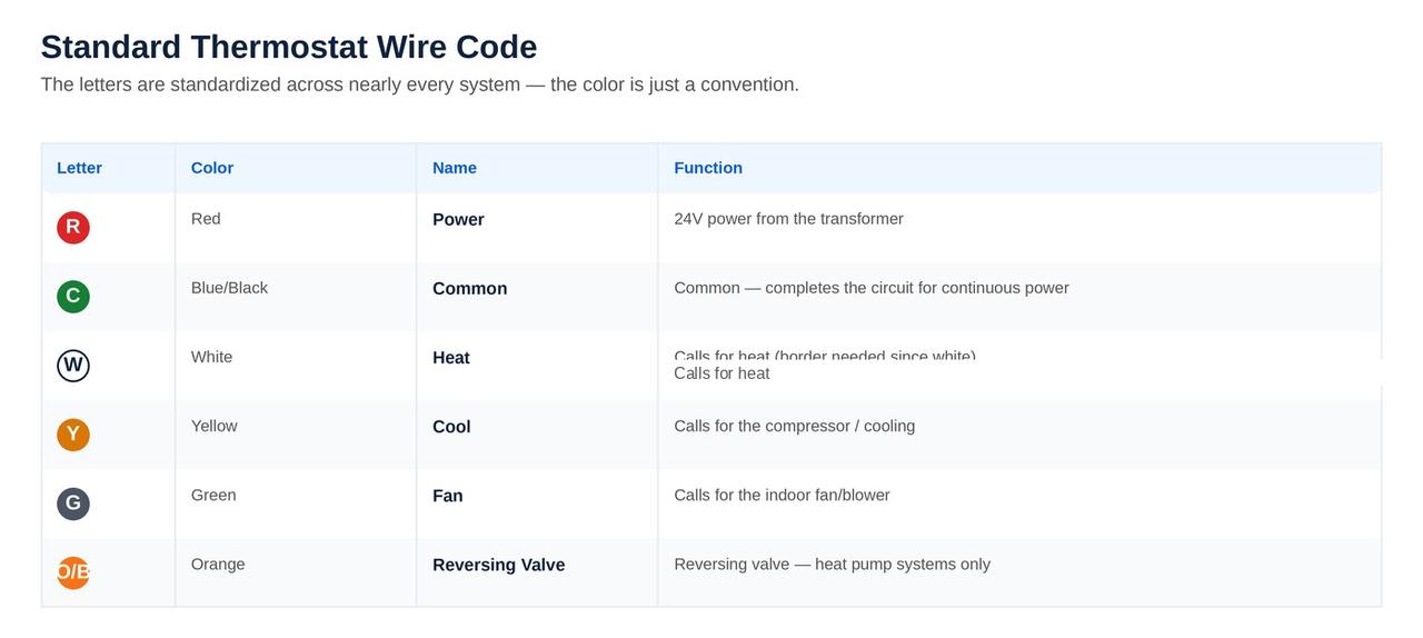
Thermostat wiring letters and what they usually mean

The table below describes common North American low-voltage conventions. It is a diagnostic reference, not permission to force every wire into the same letter on every thermostat. The exact thermostat and equipment manuals control when labels are combined, renamed, internally jumped, or assigned through software.

TerminalTypical functionWhat a problem can look likeImportant caution
R24-volt control power, often from a single transformerBlank display, no calls, intermittent resetsDo not short R to C or assume R can be bridged to every power terminal
RcCooling-transformer powerCooling side dead while heating may workMay be internally joined to R on one-transformer systems; separate on some two-transformer systems
RhHeating-transformer powerHeating side dead while cooling may workA separate Rh conductor can indicate a dual-transformer system
C24-volt common return for continuous thermostat powerBlank screen, reboots, Wi-Fi drops, relay chatterCommon is not earth ground or household neutral
Y / Y1First-stage compressor or cooling callBlower runs but outdoor unit does not startThe call may pass through a board, zone panel, float switch, or delay
Y2Second-stage compressor or coolingSystem cools weakly or never reaches higher capacityThermostat and equipment must both support and be configured for staging
GIndoor fan requestNo fan in Fan On mode or no blower with coolingSome furnaces control the fan internally during heat; G behavior varies
W / W1First-stage conventional heatFurnace does not start or wrong heat sequenceMany heat-pump applications do not use W as ordinary first-stage heat
W2Second-stage conventional heat or combined AUX/W2 functionSecond-stage heat never starts or starts too earlyIts role depends on conventional versus heat-pump configuration
O/BHeat-pump reversing-valve commandHeating in Cool mode or cooling in Heat modeO and B describe opposite energizing logic; installer setup must match the equipment
AUXSupplemental heat for a heat pumpWeak heat, excessive electric heat, high utility useMay be electric strips or a fossil-fuel backup depending on the system
EEmergency heat selection or relay on compatible heat pumpsNo emergency heat or compressor disabled unexpectedlyEmergency Heat is an operating mode, not just another normal stage
L / L-AEquipment fault or monitor input on some heat pumpsFault indicator unavailable or incorrect alertNot a universal power or call terminal
S / S1 / S2Remote indoor or outdoor sensorWrong displayed temperature or missing sensorSensor type and polarity requirements depend on the product
U / ACC / *Configurable accessory such as humidifier, dehumidifier, or ventilatorAccessory runs at the wrong time or not at allCan be dry contact, powered output, or software-assigned function
KManufacturer-specific wire-saving adapter connectionFan or compressor calls fail after an adapter changeUse only with the matching adapter and installation diagram
B or XMay mean reversing valve, common, or another legacy functionBlank thermostat or wrong heat-pump modeThis is one of the most dangerous labels to guess; trace it and use the exact manual

Labels beat colors

Why thermostat wire colors are only clues

Common practice often uses red for R, yellow for Y, green for G, white for W, blue or black for C, orange for O, and brown for a second stage. That convention is helpful only until it is not. Installers may use whatever conductors were available. A cable may have been spliced in an attic. A previous thermostat replacement may have reassigned colors. A wire can change color at a splice, and an unused blue conductor at the wall may not be connected to anything at the air-handler board.

Official Honeywell Home guidance explicitly says there is no standard assigning wire color to function, and official Nest and ecobee guidance instructs users to identify wires from terminal labels and, when necessary, verify where the same conductors land on the HVAC control board. That is the correct field approach: document the old terminal, trace the circuit when uncertain, and treat color as a visual aid rather than proof.

The right labeling sentence

Do not say, “The blue wire is common.” Say, “The conductor connected to C at the equipment board and C at the thermostat is common.” That wording prevents a large percentage of thermostat-installation mistakes.

System architecture

Common thermostat wiring patterns

The same terminal letter can behave differently depending on the equipment architecture. Before selecting a thermostat, count stages and identify whether control is conventional, heat pump, dual fuel, zoned, or communicating.

System typeCommon thermostat conductorsWhat the thermostat controlsMain compatibility risk
1 heat / 1 cool conventionalR, Y, G, W, and often CFirst-stage AC, blower, and furnace or electric heatMissing C, wrong fan-control setting, or mishandled R/Rc jumper
Multi-stage conventionalR, C, Y1, Y2, G, W1, W2Separate low- and high-capacity heating and cooling callsThermostat supports fewer stages or installer setup is left at one stage
Heat pump without backup heatR, C, Y, G, O/BCompressor, blower, and reversing valve in both heating and coolingO/B configured for the wrong energizing mode
Heat pump with auxiliary heatR, C, Y1, G, O/B, AUX/W2, sometimes E and Y2Heat pump stages plus supplemental or emergency heatAUX/E assignment, lockouts, staging, or excessive strip-heat operation
Dual fuelOften heat-pump terminals plus backup-heat controlHeat pump above balance point and furnace below a configured changeover conditionRunning compressor and fossil-fuel heat together when the equipment is not designed for it
Two-transformer conventionalRc, Rh, Y, G, W, and a system-specific commonSeparate cooling and heating control-power circuitsImproperly bridging Rc and Rh or using the wrong common
Zoned HVACThermostat wires terminate at a zone panelA zone demand; the panel coordinates dampers and equipmentAdapter installation, panel power limits, and calls that are altered by panel logic
Communicating or proprietaryOften 2–4 wires on data or numbered terminalsDigital communication, equipment status, staging, airflow, and diagnosticsA standard thermostat cannot directly replace the communicating controller
Line-voltage or millivoltNot standard R/C/Y/G/W control wiringBaseboard, wall heat, fireplace, or specialized equipmentElectrical hazard and incompatible thermostat power requirements

In a zoned home, the thermostat may be correctly calling for cooling while the zone panel intentionally delays equipment, closes a damper, or prioritizes another demand. In a communicating system, the wall control may also set blower airflow, compressor capacity, humidity targets, and fault reporting. Replacing it with a basic R/Y/G/W thermostat can remove features or may not be possible without an interface and system reconfiguration.

Control power

R, Rc, Rh, and thermostat jumper wires

R is the source side of the 24-volt control circuit. Older thermostat bases commonly have separate Rc and Rh terminals joined by a small metal jumper when one transformer powers both heating and cooling. Many newer thermostats use an internal electronic jumper, a slider tab, or a single R terminal. That means the visible jumper on the old thermostat may not be transferred to the new one.

One-transformer systems

Most split residential systems use one transformer in the furnace or air handler. One R conductor may have been placed on R, Rc, or Rh depending on the old thermostat. The new thermostat’s instructions determine which power terminal to use and whether an internal R slider or software option must be set for one wire.

Two-transformer systems

Some homes use separate heating and cooling transformers. Two real wall conductors may land on Rc and Rh. Those are not the same as a short factory jumper. The thermostat must support isolated transformer inputs, and the common connection must follow the product and system diagram. Bridging transformer secondaries can open fuses, damage transformers, or create unstable control voltage.

How to recognize a jumper

A jumper is usually a short piece of wire, staple-shaped conductor, or built-in tab connecting adjacent terminals on the old thermostat. It does not disappear into the wall. A true Rc or Rh system conductor leaves the thermostat cable and can be traced toward the equipment. Official Nest, ecobee, and Honeywell Home documentation all treat jumper handling as model-specific, so the correct instruction is always based on the new thermostat’s installation guide.

Never “just add a jumper” to make a dead system work

A missing cooling or heating call can be caused by a fuse, transformer, safety, broken wire, board, thermostat relay, or equipment failure. Adding an R-to-Rc/Rh jumper without confirming the system architecture can combine circuits that were meant to remain separate.

Continuous thermostat power

C-wire problems, unused conductors, and power adapters

The C wire is the common side of the HVAC transformer’s 24-volt circuit. With R, it gives many smart thermostats continuous power for the display, Wi-Fi radio, sensors, and control electronics. C does not mean “cooling,” and common is not the same as household neutral, equipment ground, or the metal cabinet.

A spare conductor is not automatically a C wire

A cable may contain an unused blue or brown conductor behind the thermostat. It becomes a usable common only when its other end is identified and connected to the correct C, COM, or 24V common point at the furnace, air handler, zone panel, or approved equipment interface. Official Resideo documentation specifically notes that there is no universal color for common.

Approved C-wire solutions

Use an unused conductor

Often the cleanest solution when the cable has a spare wire and the equipment board has an appropriate common terminal. Both ends must be connected correctly, and existing common wires must remain secure.

Install new thermostat cable

The most direct long-term fix when access allows. It preserves full fan and staging control and avoids adapter limitations.

Use a manufacturer-approved adapter

Products such as a Resideo C-wire adapter or ecobee Power Extender Kit combine or remap control functions according to a specific wiring diagram. They are not generic jumpers.

Use equipment-interface architecture

Some thermostats communicate with an interface module near the equipment, reducing the number of wall conductors. The module and thermostat must be a compatible system.

Zoned systems, dual-transformer systems, heat pumps, and multi-stage equipment can make adapter installation more complex. A thermostat that reboots when cooling starts, repeatedly drops Wi-Fi, goes blank when a relay energizes, or causes contactor chatter may have a marginal power circuit rather than a software problem. Use the blank thermostat screen guide for power-path symptoms and the Honeywell thermostat guide, Nest thermostat guide, or ecobee thermostat guide for brand-specific behavior.

Do not use the equipment cabinet as C

The transformer secondary may be referenced or bonded in a particular way, but the correct thermostat common is the designated low-voltage common terminal in the approved wiring diagram. Improvised grounding can create faults, nuisance operation, or equipment damage.

Heat-pump changeover

O/B thermostat wiring: why a heat pump can run in the wrong mode

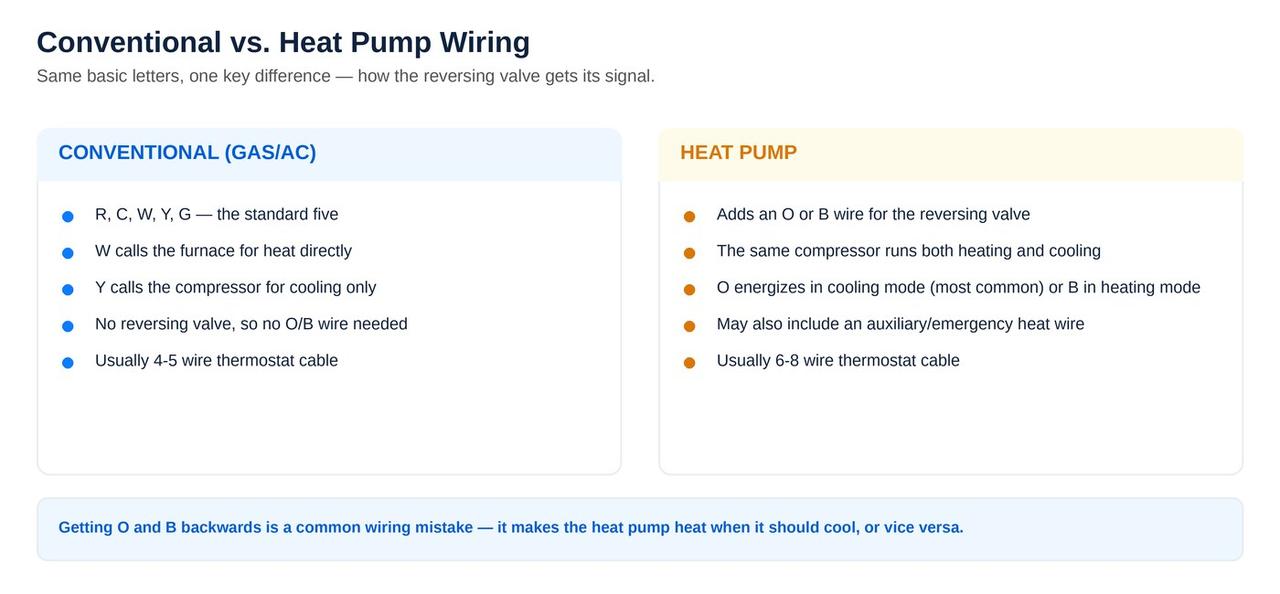
A heat pump uses the refrigeration system for both cooling and heating. The O/B circuit controls the reversing valve that changes refrigerant flow. Many systems energize the valve in cooling and are configured as O. Some systems energize it in heating and are configured as B. The thermostat’s installer setting must match the outdoor equipment.

If O/B is wired correctly but configured backward, the compressor and blower may run normally while the supply air is the opposite temperature from the selected mode. A homeowner can mistake this for a failed compressor, refrigerant problem, or electric-heat fault. The safest response after a thermostat change is to stop extended operation, identify the heat-pump model, and correct the reversing-valve setting before repeated testing.

O/B is not conventional W

On a conventional furnace, W calls heat. On a heat pump, compressor heating still uses Y, and O/B positions the reversing valve. Supplemental heat is typically assigned to AUX or W2/AUX. Official Honeywell Home installation guidance warns that ordinary W should not be used as the primary heat call on many heat-pump applications. A combined W-O/B terminal on an old thermostat must be interpreted according to system type, not copied blindly.

O and B labels can conflict with older common-wire labels

Some legacy systems use B or X for common, while many heat pumps use B for reversing-valve logic. That ambiguity is a strong reason to trace the wire to the control board. A wrong guess can create a dead thermostat, incorrect mode operation, or a direct short.

Wrong-temperature air after installation is a configuration emergency—not a reason to keep experimenting

Turn the system off at the thermostat and verify equipment type, terminal assignment, and the O/B energizing setting. Running auxiliary heat against active cooling or operating a heat pump in the wrong mode can waste energy and stress equipment.

Heating stages

W2, AUX, E, Y2, and multi-stage thermostat setup

Terminal count is only half of multi-stage compatibility. The thermostat must also be told what equipment it controls, how many compressor and heat stages exist, who controls the indoor fan, and when additional stages may operate.

Conventional W2

On a two-stage gas furnace, W1 typically requests low fire and W2 requests high fire. Some furnaces can internally stage from W1 based on time, while others use separate thermostat calls. Wiring W2 without configuring the thermostat for two-stage conventional heat can prevent or distort staging.

Heat-pump AUX

Auxiliary heat supports the heat pump when capacity is insufficient, during some recovery periods, or under configured outdoor conditions. In many Texas air handlers, AUX operates electric resistance strips. Those strips can draw substantial power, so aggressive staging or incorrect setup can produce a large electric bill even though the home feels warm.

Emergency Heat

Emergency Heat is intended to bypass or disable compressor heating on compatible systems and use backup heat. It is not a faster version of Heat mode. Some thermostats use a combined AUX/E terminal and separate the behavior through software; others provide dedicated terminals. The exact equipment and thermostat diagrams decide whether AUX and E are bridged, separated, or controlled through a board.

Second-stage cooling or compressor Y2

Y2 requests additional compressor capacity on supported two-stage systems. Variable-speed and communicating systems may not expose a conventional Y2 wire because capacity is negotiated digitally. A standard thermostat connected through conventional terminals can also change how much modulation and diagnostic information remains available.

If auxiliary heat runs constantly, the home cannot reach setpoint, or the thermostat appears to short cycle equipment, compare wiring and configuration before condemning the thermostat. See thermostat not reaching the set temperature, AC short cycling, and compressor short cycling.

Label-for-label, then configure

A safe thermostat replacement sequence

This sequence is appropriate only after confirming a standard compatible low-voltage system. It deliberately avoids live-meter instructions. If any step exposes uncertainty, stop and schedule professional installation.

  1. Run the compatibility check for the exact new thermostat. Include every connected terminal, system type, stages, accessories, and whether Rc and Rh are separate conductors.
  2. Locate the old and new manuals. Screenshots and generic internet diagrams are not substitutes for the installation documents tied to the model numbers.
  3. Record current operation before shutdown. Note which modes work, whether the fan runs, whether the system is a heat pump, and any installer settings that can be viewed safely.
  4. Turn off HVAC power. Shut down the indoor equipment and outdoor unit according to the system’s service arrangement. Confirm the thermostat display and equipment stop as expected.
  5. Photograph the original wiring. Capture terminal letters, jumpers, splices, and unused conductors. Take more than one angle.
  6. Label each wall conductor by its old terminal. A wire on Y gets a Y label regardless of color. Mark separate Rc and Rh conductors distinctly.
  7. Distinguish jumpers from wall wires. Do not transfer an old R-Rc jumper unless the new thermostat’s instructions specifically call for it.
  8. Keep the cable from falling into the wall. Secure it gently without nicking insulation or allowing bare copper to touch other conductors.
  9. Connect only documented conductors. Do not attach an unused wire merely because the new thermostat has an empty terminal. If adding C, connect and verify both ends through the approved method.
  10. Inspect terminal engagement. Copper should be clamped securely with minimal exposed conductor. Loose strands and excessive bare copper can create intermittent faults or shorts.
  11. Restore panels and power before setup. A blower-door switch may keep the thermostat blank until the furnace or air-handler panel is completely seated.
  12. Configure before operating. Select conventional or heat pump, stage counts, fuel type, fan control, O/B logic, auxiliary heat behavior, and accessories from the equipment information.
  13. Allow compressor-protection delays. Do not rapidly switch modes or repeatedly cycle power. Observe one controlled call at a time.
  14. Verify the complete sequence. Confirm fan, cooling, heating, second stages, and backup heat only when the system is designed and conditions allow. Stop if the equipment runs in the wrong mode, chatters, trips, smells hot, or cycles rapidly.

Failure patterns

Common thermostat wiring mistakes and what they look like

Symptom after wiringCommon thermostat-side causesOther HVAC causes to rule outBest next step
Thermostat is blankR or C loose, wrong common, power still off, base not seatedDoor switch, float switch, fuse, transformer, boardCheck safe power items; do not keep replacing fuses
Fan runs but outdoor unit does notY missing, loose, misassigned, or delayedFloat circuit, board, contactor, breaker, disconnect, capacitor, compressorVerify the cooling call through the entire control path
Outdoor unit runs but indoor blower does notG not connected or fan-control setup wrongBlower relay, board, motor, module, door switchTurn cooling off to prevent coil icing and compressor stress
Heat blows in Cool modeO/B logic wrong, system configured as conventional, wire on W instead of O/BReversing valve or heat-pump control faultStop and verify heat-pump model and O/B setup
Auxiliary heat runs constantlyWrong stage setup, AUX/E assignment, aggressive recovery, heat-pump call missingWeak heat pump, sensor, defrost, refrigerant, airflow, outdoor unit faultReview setup and test compressor heating before blaming the thermostat
Thermostat reboots or clicksWeak C connection, loose R, marginal adapter, exposed copperTransformer voltage drop, shorted coil, board, safety openingStop repeated cycling and have the 24-volt circuit tested under load
Low-voltage fuse opensR touched C or cabinet, pinched conductor, wrong terminalShorted contactor coil, wet wiring, board, damaged cableFind the short before installing another fuse
Heating works but cooling does not, or vice versaRc/Rh handling, missing Y or W, wrong equipment typeSeparate transformer fault, equipment-side control failureDetermine one- versus two-transformer architecture
System will not shut offBare conductors touching, stuck thermostat relay, wrong accessory assignmentStuck contactor, welded relay, board fault, fan-delay logicTurn the system off safely and isolate the control fault

Three mistakes that create expensive misdiagnoses

  • Changing wiring and installer settings at the same time. When the system fails, there is no known-good baseline. Make documented changes and verify each layer.
  • Assuming a valid thermostat call proves the equipment is healthy. A solid cooling icon does not prove the contactor, capacitor, motor, or compressor is operating. See AC contactor not working.
  • Replacing the thermostat to cure a safety shutdown. A clogged drain and open float can make the thermostat blank or interrupt cooling. Replacing the wall control does not clear the water. See AC drain line clogged in Spring, TX.

Measured diagnosis

Professional thermostat and low-voltage diagnostic sequence

A strong diagnostic visit treats the thermostat, wiring, safeties, control boards, and equipment as one circuit. The goal is not merely to make the screen light up; it is to prove where power and control are present, where they disappear, and whether the equipment responds correctly.

StepWhat is checkedWhat the result proves
1. Document equipmentThermostat, furnace or air-handler, outdoor unit, zone panel, heat kit, and accessory model numbersCompatibility, stage count, system type, and correct wiring diagrams
2. Inspect the original circuitTerminal assignments, jumper positions, splices, conductor condition, water, heat damage, and panel switchesWhether the fault is physical, installation-related, or safety-related
3. Verify control powerTransformer supply and nominal low-voltage output, fuse protection, R-to-C power, and voltage stability under loadWhether the thermostat has a stable source or is resetting because voltage collapses
4. Verify safetiesCondensate floats, door interlocks, board lockouts, pressure and equipment safety circuits as applicableWhether the thermostat call is intentionally interrupted
5. Verify thermostat outputsCooling, fan, heating, O/B, second-stage, auxiliary, emergency, and accessory callsWhether the thermostat relays and configuration match the demand
6. Trace calls downstreamSignal at control board, zone panel, equipment interface, contactor, relays, and outdoor unitThe exact point where a valid call stops
7. Verify equipment responseBlower operation, compressor and fan start, furnace sequence, heat strips, staging, reversing valve, and shutdownWhether the issue is control wiring or an equipment component
8. Confirm configurationSystem type, stage count, O/B logic, fan control, temperature source, cycle rates, lockouts, and accessoriesThat correct wiring is not being undermined by incorrect software setup
9. Document final operationMode-by-mode response, temperature change, delays, wiring labels, and customer settingsA repeatable repair and a baseline for future service

This sequence prevents a common failure in HVAC service: replacing a thermostat when the actual problem is a float switch, fuse, transformer, contactor coil, broken conductor, zone panel, or equipment component. The AC Diagnostic Center explains the same measured approach across electrical, airflow, refrigerant, and compressor faults.

Make the right investment

Repair the wiring, replace the thermostat, or evaluate the HVAC system?

A thermostat symptom does not automatically justify a thermostat replacement, and a thermostat replacement almost never justifies replacing the entire HVAC system by itself. The correct decision follows the failed component.

FindingUsually appropriate actionWhy
Loose terminal, damaged splice, or broken low-voltage conductorRepair or replace the wiring sectionThe thermostat may be healthy; restore a reliable circuit and label it correctly
Open float, door switch, fuse, transformer, contactor coil, or control-board faultRepair the equipment or safety faultThe thermostat is reporting or experiencing a downstream power problem
Known-good stable power and wiring, but failed display, sensor, relay, or baseReplace the thermostatThe control itself has failed after the rest of the circuit is proven
New thermostat incompatible with stages, dual transformers, accessories, or communicating controlsChoose a compatible control or install the approved interfaceA more expensive thermostat is not necessarily more compatible
Obsolete communicating control unavailable, with aging equipment and multiple major failuresCompare control retrofit, major repair, and system replacementThe decision depends on total reliability, parts availability, efficiency, comfort, and repair risk
Thermostat is old but the HVAC equipment is operating correctlyReplace only for reliability or desired featuresA thermostat upgrade can improve usability without replacing functional heating and cooling equipment

Evaluate HVAC replacement only when broader evidence supports it: age, compressor or heat-exchanger condition, repeated failures, obsolete refrigerant or controls, high repair cost, poor comfort, airflow limitations, efficiency, and parts availability. Use the Texas repair-versus-replacement guide when the thermostat diagnosis uncovers a major equipment issue.

A new thermostat cannot repair a failed AC contactor, clogged drain, broken transformer, or compressor

It can only send the correct call. Before approving replacement of any major component, ask where the control signal was measured, where it stopped, and what equipment test confirmed the failure.

Local thermostat and HVAC diagnostics

Need thermostat wiring help in Spring or North Houston?

AC Repair Expo Heating & Cooling Inc diagnoses R, Rc, Rh, C, Y, G, W, W2, O/B, AUX, E, zone-panel, transformer, fuse, float-switch, contactor, heat-pump, staging, and smart-thermostat control problems as one complete HVAC circuit.

Service areas: Spring, The Woodlands, Tomball, Cypress, Conroe, Humble, Kingwood, and North Houston.

Address: 1827 Riley Fuzzel Rd Suite C, Spring, TX 77386
Texas license: TACLB43277C

Call 832-479-2727

Manufacturer references

Official thermostat wiring and compatibility sources

Terminal behavior, jumpers, adapters, stage limits, and configuration vary by product. These official manufacturer resources were used to verify the general wiring principles in this guide. Always use the installation manual for the exact thermostat and HVAC equipment model.

Frequently asked questions

Thermostat wiring FAQs

Can I identify thermostat wires by color?

No. Red, yellow, green, white, blue, orange, and brown are common conventions, but there is no universal color standard. Identify every conductor by the terminal it was connected to and confirm the same conductor at the furnace, air-handler, heat-pump, or zone-control board. Splices and previous repairs can make color especially misleading.

What is the difference between R, Rc, and Rh thermostat wires?

R is 24-volt control power. Rc traditionally identifies power from the cooling transformer and Rh identifies power from the heating transformer. Most residential systems use one transformer, so R and Rc/Rh may be internally joined or connected by a manufacturer-approved jumper. A true two-transformer system keeps Rc and Rh separate; bridging them without the correct design can damage controls.

What does the C wire do on a thermostat?

C is the 24-volt common return that completes a continuous power circuit with R for thermostats that need equipment power. It does not directly command cooling or heating. A conductor is not a C wire merely because it is blue or unused; it must connect to the correct common terminal at the HVAC control board or approved adapter.

Can I use the G wire as a C wire?

Only through a method explicitly supported for the thermostat and HVAC system. Simply moving G to C can eliminate independent fan control and may create equipment or compatibility problems. Approved devices such as a manufacturer-specific C-wire adapter or Power Extender Kit change the circuit in a defined way. Zoned, multi-stage, heat-pump, and communicating systems need extra caution.

Why did the system start heating in Cool mode after a thermostat replacement?

The most common thermostat-related cause is an incorrect heat-pump O/B reversing-valve setting or an O/B wire placed on the wrong terminal. The thermostat may also be configured as conventional equipment instead of a heat pump. Stop extended operation and verify the outdoor-unit model, the original wiring, and whether the reversing valve is energized in cooling or heating.

What is the difference between W, W2, AUX, and E?

On conventional systems, W or W1 usually calls first-stage heat and W2 calls second-stage heat. On heat pumps, AUX calls supplemental heat and E selects emergency heat on systems designed for it. Some thermostats combine AUX and E on one terminal, while others separate them. Terminal assignment and installer configuration must match the equipment.

What should I do if the old thermostat has both O and B terminals?

Do not assume both are heat-pump reversing-valve wires. On some older controls, B or X can be common; on others, O and B represent opposite changeover-valve logic. Use the exact thermostat and equipment manuals and trace the conductors to the control board. Guessing can cause wrong-mode operation or a low-voltage short.

Can I connect two separate R wires together?

Not unless the manufacturer documentation and system design specifically require it. Two separate wall conductors on Rc and Rh can indicate separate cooling and heating transformers. Those circuits must generally remain isolated and be connected to the correct thermostat terminals with its internal jumper or slider configured for two-transformer operation.

What do numbered or A, B, C, D thermostat terminals mean?

They often indicate a communicating or proprietary control system rather than standard 24-volt calls. A conventional smart thermostat may not connect directly to those terminals. Replacement can require a compatible communicating control, an equipment interface module, or rewiring and configuration by a qualified HVAC technician.

Why is the thermostat blank after I changed the wiring?

Possible causes include HVAC power left off, an open blower-door switch, a raised condensate float, a loose R or C conductor, an unused conductor that was never connected to common at the equipment, a blown low-voltage fuse, a damaged transformer, or an incompatible thermostat. Do not keep replacing fuses or bypassing safeties without finding the fault.

Can incorrect thermostat wiring damage the HVAC system?

Yes. A short between R and C can open the control fuse or damage a transformer. Incorrectly combining transformer circuits, misplacing a common wire, or repeatedly forcing compressor starts can damage controls or equipment. Power should be off while conductors are moved, and unfamiliar, proprietary, line-voltage, zoned, dual-fuel, or multi-stage systems should be handled professionally.

When should I call an HVAC technician for thermostat wiring?

Call when terminals are unlabeled, wire colors do not match end to end, the system uses Rc and Rh separately, the thermostat has numbered or proprietary terminals, a heat pump or dual-fuel system is involved, a fuse or breaker opens again, the thermostat reboots, the contactor chatters, the equipment runs in the wrong mode, or the system does not respond after a careful label-for-label replacement.