Diagnostic roadmap
What this C-wire guide covers
- What R and C actually do
- Symptoms of missing or unstable common power
- Missing C wire versus dead C wire
- Safe homeowner checks
- The complete 24-volt power path
- Common causes of C-wire failures
- C-wire solution comparison
- Nest, ecobee, and Honeywell/Resideo
- Heat pumps, zoning, boilers, and dual transformers
- Professional diagnostic sequence
- Wiring mistakes to avoid
- Repair versus replacement guidance
- 12 C-wire FAQs
Control-power fundamentals
What the C wire actually does in a thermostat circuit
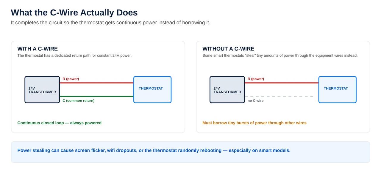
Most conventional residential HVAC controls use a transformer that reduces line voltage to a nominal 24 volts AC for the thermostat, relays, contactor, zone controls, and control board. The thermostat normally receives one side of that transformer on R. The C terminal is the common side of the same control transformer. A powered thermostat uses R and C as the two sides of its operating-power circuit.
The C wire is frequently misunderstood because the word common sounds like household neutral or ground. It is neither. C belongs to the isolated low-voltage HVAC control circuit. Connecting C to a grounding conductor, neutral, cabinet metal, or an unrelated transformer can damage the thermostat or equipment. The correct common point must come from the same transformer and control system that supplies the thermostat's R terminal unless the exact manufacturer diagram specifies another arrangement.
| Terminal | Typical purpose | Important C-wire relationship |
|---|---|---|
| R, Rc, or Rh | Nominal 24-volt control-power supply from one or two transformers | C must match the controlling transformer arrangement; Rc/Rh rules vary by thermostat and system |
| C | Common return used to power compatible thermostats and controls | Does not normally call heating, cooling, or fan operation by itself |
| Y or Y1 | Compressor or first-stage cooling call | The outdoor contactor coil commonly operates between Y and C, so a Y-circuit short or weak coil can affect control power |
| G | Indoor fan command on many conventional systems | Moving G to C without an approved method may remove independent fan control or alter blower operation |
| W, W1, or AUX | Conventional heat, auxiliary heat, or first heating stage depending on system | Heating relays and safeties can load or interrupt the same 24-volt power source |
| O/B | Heat-pump reversing-valve command | Wrong configuration can produce wrong-mode operation even when R and C power are correct |
Wire color is not terminal identity
Blue or black is often used for common, but installers can use any available conductor. A blue wire behind the thermostat may be disconnected, spliced, repurposed, or attached to the wrong terminal. Verify the terminal at every end. The thermostat wiring guide explains R, C, W, Y, G, O/B, AUX, E, staging, and jumper conventions in more detail.
A basic battery thermostat may not need continuous R-to-C power because its batteries operate the display and electronics. A Wi-Fi or smart thermostat has a larger continuous load for its screen, processor, radio, sensors, and relays. Whether a specific model can obtain that power without a dedicated C conductor is a manufacturer and system compatibility question, not a universal rule.
Recognize the pattern
Symptoms of a missing, disconnected, or unstable C wire
A missing C wire does not create one single symptom. The result depends on how the thermostat attempts to power itself, how the HVAC controls are wired, whether a battery is present, and what happens when heating or cooling energizes additional loads. Symptoms that appear only during a compressor, furnace, fan, damper, or accessory call are especially useful because they suggest that the power circuit changes under load.
| Symptom | Possible C-wire or 24-volt explanation | Other causes that must be separated |
|---|---|---|
| Thermostat screen is completely blank | No R-to-C power, disconnected common, open fuse, transformer failure, float switch, door switch, or loose base connection | Dead batteries on battery models, failed thermostat, display problem, or equipment service switch off |
| Thermostat reboots when cooling starts | Voltage collapse under Y/contactors, weak transformer, loose C, damaged cable, adapter error, or safety interruption | Control-board reset, contactor-coil short, outdoor wiring short, or condensate safety operation |
| Battery drains unusually fast | Thermostat is not receiving sufficient continuous power or C is detected but ineffective | Old battery, charging circuit failure, extreme temperature, incompatible battery, or defective thermostat |
| Wi-Fi repeatedly disconnects | Thermostat conserves power, reboots, or loses stable supply | Router coverage, network changes, app outage, firmware, or account configuration |
| Delayed, Starts in, Wait, or power alert repeats | Power interruption keeps restarting protective logic or setup tests | A normal one-time compressor protection delay after shutdown or mode change |
| Relay or contactor chatters | Marginal voltage, high-resistance connection, power-stealing interaction, overloaded transformer, or intermittent common | Weak contactor coil, board output, pressure switch, float switch, or damaged low-voltage cable |
| Heat or cooling starts unexpectedly | Miswired adapter, backfeeding, improper external transformer, loose strands bridging terminals, or incorrect Rc/Rh arrangement | Schedule, geofencing, utility program, stuck relay, shorted thermostat cable, or board fault |
| App says offline but local screen works | Power may be marginal enough to affect the radio before local control fails | Internet or cloud issue; confirm whether local heating and cooling control remains normal |
A blank display deserves the broader thermostat blank-screen diagnostic path. A thermostat that remains powered but will not command equipment belongs in the thermostat-not-working guide. Repeated starts and stops should also be compared with the smart thermostat short-cycling guide.
Do not lump these together
No C wire, a dead C wire, and unstable C-wire power are different faults
The phrase no C wire is often used for every thermostat power complaint. That can lead to the wrong repair. A home may have a usable spare conductor that simply is not connected. It may have a wire in C that is attached to nothing. It may have normal voltage with no load but a severe drop when the equipment starts. Or the entire 24-volt circuit may be off because a safety, fuse, switch, transformer, or board has opened.
No wire reaches the C terminal
The cable may have too few conductors and no spare. A new cable or approved equipment-side power accessory may be appropriate after compatibility is confirmed.
A spare wire exists behind the wall
The spare must be found at the equipment end and connected to the correct C terminal. Connecting only the thermostat end does not create power.
A wire is in C but not connected through
A splice, zone panel, equipment board, or adapter may interrupt the conductor. Continuity and terminal tracing are required with power off.
R and C are both present but there is no voltage
Check the breaker, service switch, blower door, condensate safety, low-voltage fuse, transformer primary and secondary, board, and wiring.
Power looks normal until equipment starts
A weak transformer, overloaded accessory circuit, contactor-coil problem, poor splice, loose terminal, or safety device may pull the voltage down or open the circuit.
C belongs to a different transformer or control
Dual-transformer, boiler, zone, add-on heat-pump, and mixed-control systems can be damaged by combining power sources incorrectly.
A voltage reading at one moment is not a complete diagnosis
An unloaded control transformer can show apparently normal voltage while a loose connection, failing transformer, or overloaded circuit collapses during a call. A professional compares readings at the transformer, equipment board, zone panel or interface, thermostat, and active load while the failure is occurring.
Homeowner checks
Safe checks before opening or rewiring HVAC controls
Low-voltage thermostat wiring is connected to equipment that also contains hazardous line voltage, moving blowers, hot surfaces, capacitors, and refrigerant components. Homeowners can document visible conditions and basic operating behavior. Live electrical testing and internal rewiring should be left to someone who can isolate both the line-voltage and low-voltage circuits correctly.
- Record the thermostat model and exact message. Photograph the screen, app alert, wire report, help code, or repeated startup sequence. Product families that look similar can have different power requirements and terminal layouts.
- Watch when the failure occurs. Note whether the thermostat is blank all the time, loses power only during cooling, reboots during heat, drops Wi-Fi at random, or fails when a zone damper or accessory operates.
- Check ordinary HVAC power controls. Confirm the thermostat is set appropriately, the HVAC breaker is not tripped, the furnace or air-handler service switch is on, and the blower door is seated. Do not repeatedly reset a breaker that trips again.
- Look for water and a raised condensate float. A backed-up drain can intentionally interrupt thermostat power or cooling. Do not push, tape, or jumper the float switch. Use the clogged AC drain-line guide.
- Inspect only accessible thermostat connections with power off. If the thermostat manufacturer permits removal from the wall plate, look for a conductor fully seated in C and take clear photographs. Do not let bare conductors touch each other or disappear into the wall.
- Compare both ends before changing anything. A spare wire behind the thermostat is not useful until the corresponding conductor is identified at the furnace, air handler, zone panel, or interface. If the equipment compartment must be opened, turn off power and understand that a door switch may also affect control power.
- Restore the original configuration if uncertain. Do not trial-and-error multiple terminal combinations. Labeling by terminal and preserving photographs prevents a power complaint from becoming a heat-pump, staging, or equipment-control problem.
- Stop operation for unsafe symptoms. Shut the system off for smoke, burning odor, arcing, rapidly chattering relays, a recurring fuse or breaker failure, water near energized equipment, or compressor attempts only seconds apart.
Never jumper R directly to C
R and C are opposite sides of the transformer secondary. A direct jumper is effectively a short circuit and can open the low-voltage fuse, overheat wiring, damage the transformer, or damage a control board. Do not substitute a larger fuse after a short. Find the fault.
Follow the complete circuit
How 24-volt power reaches the thermostat
The thermostat is near the end of a power path that begins well before the wall. A complete diagnosis accounts for every device that can remove line power, generate control power, protect the circuit, route R and C, or interrupt the thermostat. The exact order differs among furnaces, air handlers, package units, boilers, zone systems, and communicating equipment.
Devices that may interrupt the apparent C-wire circuit
| Device or connection | How it affects thermostat power | Diagnostic clue |
|---|---|---|
| HVAC breaker or service switch | Removes primary power from the transformer and equipment | Thermostat is blank and the indoor unit is silent; a recurring trip requires electrical diagnosis |
| Blower-door switch | Often removes furnace or air-handler power when the panel is open or loose | Thermostat dies after filter or service work; cabinet panel may not be seated |
| Condensate float switch | May interrupt R, Y, or equipment power when water rises | Power loss or cooling interruption appears with a full pan, wet switch, or clogged drain |
| Low-voltage fuse | Opens after a short or overcurrent in thermostat, outdoor, accessory, or control wiring | Thermostat went blank after installation, panel work, or outdoor wiring damage |
| Transformer | Creates the control voltage and must support the connected VA load | No secondary voltage, overheating, hum, or voltage that falls excessively under load |
| Zone panel or equipment interface | May provide thermostat R/C, translate calls, control dampers, or isolate equipment | Only one zone fails, panel LEDs reset, dampers chatter, or C was taken from the wrong board |
| Splices and thermostat cable | Loose, corroded, stapled, pinched, or broken conductors add resistance or open intermittently | Movement, humidity, vibration, attic heat, or a particular call changes the symptom |
| Outdoor contactor or relay coil | An abnormal coil or cable fault can load or short the Y-to-C circuit | Thermostat reboots or fuse opens exactly when the outdoor unit is commanded |
When a thermostat fails only as cooling starts, the problem may be far beyond the wall. The AC contactor diagnostic guide explains how the outdoor control coil fits into the Y and C circuit. The power-outage AC guide covers restart and surge-related symptoms.
What fails most often
Common causes of C-wire and smart thermostat power problems
Unused conductor never connected at the equipment
The thermostat installer finds an extra wire at the wall, lands it on C, and assumes the job is complete. The matching conductor may be wrapped around the cable jacket at the furnace or interrupted at a splice. Both ends must reach the same control common.
Loose terminal or poor wall-plate connection
A conductor may be inserted over insulation, barely captured by a spring terminal, broken at the stripped end, or pushed behind the plate when the thermostat is mounted. A connection can pass a light test and open as the plate flexes or temperature changes.
Damaged thermostat cable
Staples, nails, rodents, attic work, water, corrosion, sharp cabinet edges, and repeated bending can damage one or more conductors. An intermittent common may fail only with vibration or thermal expansion. New cable can be more reliable than repeated hidden-splice repairs.
Miswired C-wire adapter or power connector
Equipment-side accessories must be matched to the thermostat and exact wiring diagram. Reversed conductors, wrong equipment terminals, incompatible staging, an omitted common, or installing the device at the wrong control point can create reboots or incorrect equipment calls.
Blown low-voltage fuse
A wire touching C, cabinet metal, another bare conductor, or an outdoor short can open the board fuse. Replacing the fuse without locating the short may blow the replacement immediately and can damage more expensive components if the wrong rating is used.
Weak or overloaded transformer
Smart thermostats, zone dampers, relays, humidifiers, UV devices, air cleaners, contactors, and multiple controls can share one transformer. Added load, a failing transformer, or excessive voltage drop can leave enough power at rest but not during operation.
Condensate safety or door switch opening
The thermostat may be perfectly wired while an intentional safety removes power. A float switch can create intermittent shutdown as water sloshes or drains. A loose blower door can open its switch after filter replacement or service.
Incorrect transformer common
Heat-only boilers, separate cooling systems, add-on heat pumps, two-transformer air handlers, and zone panels can have more than one R and common reference. Mixing them can damage controls or create unpredictable operation.
Zone-panel or equipment-interface failure
Some thermostats are powered from a zone panel or equipment interface rather than directly from the furnace board. A failing panel transformer, output, damper load, or communication module can affect one thermostat, every thermostat, or only specific calls.
Control board or fuse-holder resistance
Heat-damaged terminals, cracked solder joints, loose plugs, oxidized fuse blades, and weak board connections can cause intermittent voltage loss. The visible thermostat symptom may disappear when the cabinet is opened or wiring is moved.
A repeated low-voltage failure should be treated as a circuit diagnosis, not as a sequence of thermostat replacements. If the entire AC fails to start, compare this article with AC running but not cooling, AC breaker-tripping diagnostics, and the main AC Diagnostic Center.
Choose the correct remedy
C-wire solutions compared
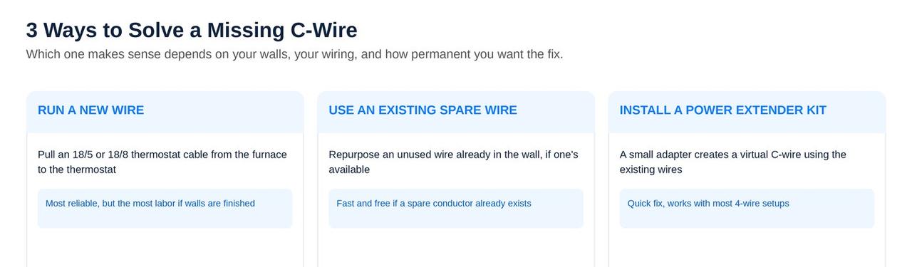
The best solution is the one that provides stable, correctly referenced power without sacrificing equipment functions or violating the thermostat's compatibility rules. The cheapest-looking option can become expensive if it causes false calls, disables fan control, conflicts with a second transformer, or conceals a failing HVAC circuit.
| Solution | Best use | Advantages | Limitations and checks |
|---|---|---|---|
| Connect an existing spare conductor | A continuous unused conductor exists from thermostat to the correct control board or panel | Direct, simple, and usually preserves every original control function | Confirm both ends, every splice, cable condition, correct common, and stable voltage under load |
| Run new thermostat cable | Cable is damaged, has too few conductors, future stages or accessories are expected, or hidden splices are unreliable | Clean long-term solution with spare conductors for service and future equipment | Wall access, attic routing, firestopping, protection from staples and heat, and code-compliant installation |
| Manufacturer-approved power accessory | The exact thermostat and HVAC system support a Nest Power Connector, ecobee PEK, Resideo adapter, or another specified device | Can create stable thermostat power without opening finished walls | Model compatibility, equipment type, terminal count, zone panels, dual transformers, staging, and exact installation diagram |
| Repair the 24-volt power source | The existing C circuit is correct but a fuse, transformer, board, splice, switch, or terminal fails | Corrects the root fault for the thermostat and all connected controls | Find why a fuse or transformer failed; do not simply increase fuse size or transformer capacity without a load analysis |
| Correct condensate or safety operation | A float, door switch, limit, or other safety intentionally interrupts the circuit | Restores power while preserving protection | Repair the water, airflow, panel, or safety condition; never permanently bypass the device |
| Approved external transformer | Only when explicitly supported by the thermostat manufacturer and exact system design | May power certain isolated applications without new cable | Second-transformer conflicts, Rc/Rh arrangement, boiler or cooling isolation, polarity/reference, and unsupported backfeeding risk |
| Choose a different compatible thermostat | The desired thermostat cannot be supported economically or safely by the existing control system | Avoids forcing an incompatible product onto proprietary or limited wiring | Verify equipment functions, heat-pump staging, accessories, zoning, and future needs before purchase |
Why pulling new cable is sometimes the most economical repair
A power adapter can be excellent when it is approved and installed correctly. It is not automatically better than wire. When a cable is damaged, has hidden splices, lacks conductors for staging, or must support future heat-pump and accessory controls, a new multi-conductor cable can eliminate several failure points at once. It also makes later diagnostics easier because each function has a dedicated, traceable conductor.
Why a larger transformer is not a universal fix
A transformer should be sized for the verified connected load and protected correctly. Replacing a failing transformer with a properly rated part can be necessary. Installing a larger transformer without finding a short, overloaded coil, stalled damper, miswired accessory, or excessive combined VA load can let damaged wiring overheat or move the failure to another component. Measure and calculate before upsizing.
Manufacturer-specific power methods
Nest, ecobee, and Honeywell/Resideo C-wire guidance
Smart thermostat brands do not use one universal no-C-wire solution. Product generations within the same brand can also differ. Always identify the exact thermostat, base, software setup path, HVAC equipment, and wiring before applying a diagram.
Google Nest: C wire or Nest Power Connector when stable power is needed
Google explains that Nest thermostats are designed to use little power and may operate without a dedicated C wire in many installations. Google also states that some systems require C or a compatible Nest Power Connector, and the setup app may identify the need through compatibility checks or a power test. Google lists power-related symptoms such as rapid battery drain, repeated Wi-Fi disconnection, power help codes, or features disabled because power is insufficient. The Power Connector is installed at the equipment side according to the diagram for the system, not as a generic jumper at the thermostat.
Use the dedicated Nest thermostat problems guide for delayed messages, wiring detection, low battery, Wi-Fi, sensors, and HVAC control symptoms.
ecobee: reliable C connection or compatible Power Extender Kit
ecobee documents installation with a direct C wire and offers a Power Extender Kit method for compatible systems that lack a usable common conductor. The PEK is an equipment-side device that reassigns functions through its specified terminals; it is not the same as simply moving G to C. ecobee's compatibility notes and installation flow should be followed for the exact thermostat model. A rebooting ecobee also requires diagnosis of safeties, transformer capacity, and power interruptions because a PEK cannot fix a failing furnace, float switch, or overloaded control circuit.
Use the ecobee thermostat problems guide for black screens, reboots, PEK wiring, sensor behavior, thresholds, heat-pump setup, and equipment calls.
Honeywell Home and Resideo: verify model requirements and approved adapter
Honeywell Home and Resideo support material for current Wi-Fi thermostat families commonly instructs users to look for a connected C wire, check for an unused conductor that can be connected at both ends, use the specified C-wire adapter in supported applications, or contact a professional. Some current installation documentation describes the THP9045A adapter when the system has the required Y and G wiring. Other thermostats may be battery powered, use an equipment interface, or have different requirements. The exact manual controls.
Use the Honeywell thermostat problems guide for blank screens, batteries, Wait, Recovery Mode, holds, Wi-Fi, O/B, auxiliary heat, and local HVAC control.
Do not cross-install brand accessories
A Nest Power Connector, ecobee PEK, and Resideo C-wire adapter are designed around their manufacturers' compatible thermostat and wiring logic. They are not interchangeable labels for the same generic device. Use only the exact accessory and diagram approved for the thermostat and system.
Systems that require extra care
Heat pumps, zoning, boilers, dual transformers, and communicating controls
Heat pumps and auxiliary heat
A heat-pump thermostat may control Y, O/B, G, AUX/W2, E, and multiple stages in addition to receiving R and C power. A no-C-wire workaround that consumes or combines a conductor can interfere with auxiliary heat, emergency heat, second-stage compressor, or fan functions. Incorrect O/B configuration can make the system heat in cooling mode or cool in heating mode even though thermostat power is stable. Confirm every function before selecting an adapter.
Zoned systems
In a zoned home, thermostats often receive R and C from the zone panel rather than directly from the furnace or air-handler board. The panel may have its own transformer or share equipment power. Multiple thermostats, damper motors, bypass controls, and relays increase the total load. A zone that reboots only when dampers move may indicate transformer capacity, panel, damper, or wiring trouble rather than an individual thermostat. Use the panel manufacturer's thermostat and power rules.
Separate heating and cooling transformers
Some systems have one transformer for heating and another for cooling. Older thermostats may show separate Rh and Rc terminals with or without a jumper. Smart thermostats handle this arrangement differently. Connecting C from one transformer while using R from the other can create no power, cross-circuit current, or component damage. Do not add a jumper that the thermostat does not specify.
Boilers and heat-only systems
Two-wire boiler controls may switch a heat call without providing a conventional C conductor at the wall. The boiler may use dry contacts, an isolation relay, a zone valve, or a transformer shared across zones. A supported power connector, isolation solution, or additional cable may be required. Never assume that a terminal labeled C on one boiler control is intended to power the selected thermostat without checking the manufacturer diagram.
Communicating and proprietary systems
Communicating HVAC systems may use data terminals, equipment interface modules, proprietary buses, or only a few conductors carrying both power and communication. Replacing the original control with a conventional smart thermostat can remove variable-capacity, humidity, diagnostics, zoning, or staging functions even if a nominal R and C can be found. Compatibility should be evaluated at the system level, not just by counting wires behind the old control.
Package units and add-on accessories
Package units, economizers, dehumidifiers, ventilation controls, humidifiers, UV devices, and relay panels can add loads or alternate control paths. A thermostat that worked before an accessory was installed may reveal a transformer load or wiring problem afterward. Identify all connected low-voltage devices during diagnosis.
Evidence before parts
Professional C-wire and 24-volt diagnostic sequence
A professional diagnosis does more than confirm that a wire is present in C. It proves the identity, continuity, voltage, load performance, safety path, and equipment response of the complete circuit. Measurements are taken with the correct power state and appropriate electrical safety practices.
- Identify the thermostat and HVAC architecture. Record exact model numbers, equipment type, stages, heat-pump O/B logic, accessories, zone controls, communicating interfaces, and whether one or two transformers are used.
- Document the original wiring at every control point. Photograph thermostat terminals, equipment board, zone panel, adapter, splice point, float switches, outdoor low-voltage terminals, and any isolation relays before disconnecting conductors.
- Verify primary power and safety switches. Confirm the indoor equipment has correct line power, the service and door switches are closed, and condensate or other safeties are not intentionally opening the control circuit.
- Inspect the low-voltage fuse and transformer. Check fuse rating and connection, transformer primary input, secondary output, visible heat damage, and evidence of a downstream short. A blown fuse is a symptom that requires a cause.
- Identify the correct R and C reference. Determine which transformer powers the thermostat and whether a zone panel or interface supplies the wall control. Never combine commons by assumption.
- Test conductor continuity with power isolated. Verify the C conductor and other relevant wires end to end, account for splices, and check for shorts between conductors or to cabinet metal. Wiggle and thermal conditions may be needed for an intermittent cable fault.
- Measure R-to-C power at multiple locations. Compare equipment-board, zone-panel, adapter, and thermostat readings. Residential controls are nominally 24 volts AC, but acceptable readings and loaded behavior must be judged against equipment specifications and circuit conditions.
- Repeat measurements under load. Observe power while fan, compressor contactor, heating relay, reversing valve, auxiliary heat, dampers, humidifier, or other accessories energize. A voltage collapse or intermittent open under load is more meaningful than a normal idle reading.
- Measure or calculate connected control load. Compare transformer VA capacity with thermostats, relays, contactors, dampers, panels, and accessories. Check for an abnormal coil or motor drawing more than intended.
- Verify thermostat output and equipment response. Confirm that the thermostat stays powered and sends the correct Y, G, W, O/B, AUX, and stage calls, then trace each call through safeties and boards to the controlled component.
- Install the selected C-wire solution and retest every mode. Confirm cooling, heating, fan, staging, auxiliary heat, emergency heat, zoning, schedules, sensors, Wi-Fi, and protective delays. Check that no function was lost to create power.
- Record final voltage, wiring, and configuration. Label adapters and spare conductors, update diagrams, secure the cable, close panels, and provide the homeowner with the exact thermostat and accessory model information.
| Test observation | What it suggests | What it does not prove |
|---|---|---|
| R-to-C power is absent at the equipment board | Primary power, switch, fuse, transformer, board, or safety-path fault | That the thermostat or wall cable is defective |
| Power exists at board but not thermostat | Open conductor, splice, panel, adapter, or terminal between equipment and wall | That a new thermostat will fix the circuit |
| Power is normal at rest and drops on Y call | Loaded voltage drop, transformer capacity, contactor coil, outdoor cable, adapter, splice, or safety issue | That the C conductor alone is the only problem |
| Stable R/C power but thermostat reboots | Thermostat base, connector, electronics, firmware, or model-specific power issue after wiring is verified | That the HVAC equipment is free of separate operating faults |
| Thermostat stays powered but cooling stops | Y-call interruption, float, board, zone panel, contactor, pressure protection, overload, or refrigeration/electrical fault downstream | That C-wire power caused the shutdown |
When the thermostat remains powered and the compressor itself cycles or overloads, use the compressor short-cycling guide. When the entire system starts and stops rapidly, use the AC short-cycling guide.
Avoid creating a second problem
C-wire installation mistakes that can damage controls or disable HVAC functions
| Mistake | Why it is risky | Correct approach |
|---|---|---|
| Assuming blue means C | The conductor may be unused, spliced, or assigned to another function | Trace terminals at both ends and through every panel or splice |
| Jumping R to C | Directly shorts the transformer secondary | Never jumper R to C; diagnose missing voltage or continuity correctly |
| Using cabinet ground or household neutral as C | C is an HVAC transformer reference, not a grounding or neutral conductor | Use the common from the correct control transformer or approved interface |
| Moving G to C without an approved device | Can remove fan control, alter cooling airflow, or backfeed circuits | Use dedicated wire or a specified adapter designed for the system |
| Adding an external transformer to random R/C terminals | Can parallel or oppose transformers and damage thermostat or boards | Use only a manufacturer-supported isolated wiring method |
| Bypassing a float or door switch | Removes water-damage or equipment-access protection | Repair the drain, panel, switch, or underlying condition |
| Installing a larger fuse | Allows wiring or board traces to carry more current than intended | Use the specified rating and locate the short or overcurrent |
| Combining commons from two transformers | Can create circulating current, cross-power equipment, or destroy controls | Identify transformer architecture and follow the exact dual-transformer diagram |
| Ignoring heat-pump or accessory conductors | A workaround may sacrifice O/B, AUX, E, stage two, dehumidification, or ventilation | Verify every current and future function before choosing a method |
Recurrent fuse failure means stop
Do not continue feeding fuses into a shorted control circuit. A pinched thermostat cable, outdoor wire rub, miswired adapter, contactor-coil fault, humidifier connection, or bare conductor can repeatedly open the fuse. Protect the transformer and board by locating the fault before restoring operation.
Spend money on the proven fault
Repair the wire, replace the thermostat, or replace HVAC equipment?
A missing common conductor is usually a controls problem, not a reason to replace an otherwise serviceable AC or heating system. The decision should follow the failed component and the broader condition of the equipment.
| Finding | Usually favors | Decision notes |
|---|---|---|
| Continuous spare conductor is available | Connect and label the spare as C | Verify both ends, correct transformer common, and operation under all calls |
| Cable has too few conductors or hidden damage | Run new thermostat cable | Select enough conductors for stages, heat pump, accessories, and future service |
| Compatible system but no route for new wire | Approved manufacturer power accessory | Confirm exact thermostat, equipment, zoning, and transformer compatibility |
| Stable correct R/C reaches thermostat but electronics fail | Replace thermostat or wall base | Preserve installer settings and confirm the replacement supports all equipment functions |
| Fuse, transformer, board, safety, or zone panel loses power | Repair the HVAC control circuit | Find the reason for failure; a new thermostat would inherit the same problem |
| Communicating system would lose major functions | Retain compatible communicating control or engineered interface | Do not downgrade variable capacity, humidity, diagnostics, or zoning merely to use a preferred app |
| Older HVAC has multiple major failures and obsolete controls | Compare comprehensive repair with system replacement | C-wire absence alone is not the reason; age, reliability, efficiency, refrigerant, major component condition, and repair economics drive the decision |
For whole-system economics, use the Texas repair-versus-replacement guide. A good thermostat-power diagnosis prevents both unnecessary thermostat purchases and premature HVAC replacement.
Official manufacturer references
Current Nest, ecobee, and Honeywell/Resideo support sources
Product requirements can change by model and software generation. These official references were reviewed for this article. Use the installation flow and manual for the exact thermostat in the home.
- Google Nest: Learn about the common or C wire
- Google Nest: Nest Power Connector
- Google Nest: Identify a thermostat wire
- Google Nest: Fix an undetected or unconfigured wire
- ecobee: Install a thermostat with a C wire
- ecobee: Install the Power Extender Kit when there is no C wire
- ecobee: Identify thermostat wires
- ecobee: Troubleshoot thermostat power
- Honeywell Home: How the C wire works
- Resideo documentation: Thermostat power options and C-wire adapter
- Honeywell Home: Thermostat support and compatibility resources
C-wire frequently asked questions
Frequently asked questions
What is a C wire on a thermostat?
The C wire is the common side of a nominal 24-volt alternating-current HVAC control circuit. R supplies one side of transformer power and C provides the return path that lets a compatible thermostat receive continuous operating power. The C wire normally does not command cooling, heating, or fan operation by itself. It is not the same as household neutral, equipment ground, or a safety grounding conductor. Terminal function must be confirmed at both the thermostat and the furnace, air handler, boiler control, zone panel, or approved interface.
Is the blue thermostat wire always the C wire?
No. Blue is commonly used for C, but thermostat wire colors are conventions rather than proof. A blue conductor may be unused, spliced to another function, disconnected at the equipment, or connected incorrectly. A different color may be serving as C. Identify the conductor by the terminal where it lands at the thermostat and at the controlling equipment, and account for every splice or zone panel between those points. Do not connect a wire to C based only on color.
Can a smart thermostat work without a C wire?
Some thermostat and HVAC combinations can operate without a dedicated C conductor, while others require a C wire or an approved power accessory. Compatibility depends on the thermostat model, equipment type, number of conductors, transformer arrangement, zoning, and available control paths. A thermostat that powers up without C is not automatically receiving stable power under every call. Battery drain, reboots, Wi-Fi drops, delayed messages, chattering, or unexpected equipment operation can indicate that a proper C-wire solution is needed.
How do I know whether my C wire actually has power?
A conductor in the C terminal is useful only when it connects to the correct common point and the R-to-C circuit remains stable. A qualified technician verifies the equipment transformer and fuse, identifies the controlling R and C, checks continuity with power off, and measures alternating-current voltage at the equipment and thermostat with power restored. The measurement must also be observed while heating, cooling, fan, staging, dampers, and accessories operate because a loose connection or overloaded transformer may look normal at rest and fail under load.
Why does my thermostat go blank or reboot when the AC starts?
A blank screen or reboot at startup often means the thermostat loses its R-to-C power path when the cooling circuit is energized. Causes can include a loose conductor, high-resistance splice, damaged cable, miswired adapter, weak transformer, overloaded transformer, opening condensate float switch, blower-door switch, low-voltage fuse connection, zone-panel fault, control-board problem, or a short in the Y or contactor circuit. The correct repair is to find where voltage disappears under load rather than repeatedly restarting the thermostat.
Does a Nest thermostat need a C wire?
Google states that many Nest installations can obtain enough consistent power without a dedicated C wire, but some systems require a C wire or compatible Nest Power Connector. Google specifically identifies certain heating-only, cooling-only, zone-controlled, and heat-pump systems as examples that may require a stable power solution, and the setup app may perform a power test. Follow the wiring diagram for the exact Nest model and system. Do not assume that a previous Nest model and a replacement model use identical terminals or power requirements.
Can ecobee work without a C wire?
ecobee thermostats require a reliable C connection or a compatible Power Extender Kit arrangement. When a suitable spare conductor is unavailable and the system meets the requirements, ecobee documents installing its PEK at the furnace control board so the existing conductors can provide the necessary functions. PEK compatibility is model- and system-specific. It should not be improvised on incompatible equipment, communicating systems, unsupported multi-speed fan arrangements, or wiring that has not been positively identified.
What are the Honeywell Home and Resideo options when there is no C wire?
Honeywell Home and Resideo documentation for current Wi-Fi thermostat families commonly directs users to check for an unused conductor, use the specified C-wire adapter when the exact system and thermostat support it, or contact an HVAC professional. Some documented applications use a THP9045A adapter when appropriate Y and G conductors are present. Requirements vary by thermostat and equipment. The exact installation manual and compatibility tool should control the decision rather than a generic online diagram.
Can I use a plug-in transformer as a C-wire substitute?
Only when the thermostat manufacturer explicitly supports that power method for the exact thermostat and HVAC configuration. An external transformer introduces a second power source, so incorrect connections can place transformers in conflict, damage controls, create unpredictable calls, or defeat isolation between heating and cooling systems. Dual-transformer systems, zone panels, boilers, heat pumps, and thermostats with combined R terminals require special attention. A manufacturer-approved equipment-side power connector or a new thermostat cable is often a cleaner solution.
Can I move the G wire to C to power a smart thermostat?
Do not simply move G to C and add jumpers from a generic internet diagram. Doing so can remove independent fan control, alter cooling fan operation, create backfeeding, or conflict with furnace-board logic. Some approved adapter products intentionally combine or translate Y and G functions, but they do so through a specified device and wiring diagram. Use a spare conductor, pull new cable, or install the correct manufacturer-approved accessory after the equipment and thermostat have been identified.
Can a clogged drain line cause a C-wire or thermostat power problem?
Yes. Many Texas air handlers use a condensate float switch that interrupts R, Y, or another part of the low-voltage control circuit when water rises. If the switch interrupts thermostat power, the display may go blank or reboot and appear to have a bad C wire. If it interrupts only the cooling call, the thermostat may stay powered while the outdoor unit stops. The switch should not be bypassed. Correct the drainage problem, inspect the pan and trap, and verify the control circuit afterward.
Should I replace the thermostat, run a new C wire, or replace HVAC equipment?
Replace the thermostat when testing proves its base, power circuit, connector, or electronics are defective and the system supplies stable compatible control power. Run new thermostat cable or use an approved accessory when the thermostat is compatible but no reliable common conductor exists. Repair the transformer, fuse holder, wiring, safety, zone panel, board, or outdoor control when that equipment causes the power loss. Whole-system replacement is rarely justified by a missing C wire alone; it becomes relevant only when broader equipment age, condition, compatibility, or major repair economics support it.